

New SimpleXYZ 2026 release: our motorised microscope control software (SmartScope / Winkoms)
Over the past few weeks we've taken an important step forward with SimpleXYZ, the application that controls the microscope's XYZ stage and camera for image capture in digital pathology. The standout improvement is the new Sample Scan — see it in action in the video:
✅ Low-cost, compatible solution — runs on Windows 10 and 11 (64-bit) and Linux, developed entirely in-house at Winkoms with OpenSource tools, on SmartScope hardware and adaptable to any other motorised system.
✅ Sample Scan integrated with CapEx Snake — locates the tissue on the slide with a fast panoramic scan (4x objective) and, with a single click, sends the selected area to high-resolution capture (10x objective) without switching modules or repeating the scan.
✅ Multi-language interface — Spanish, Catalan and English, selectable from within the application itself.
✅ Background calibration and region detection (ROI) — uneven-illumination correction and manual drawing of areas of interest directly on the generated mosaic.
✅ Laplacian autofocus for CapEx Snake — initial focus is verified and automatically maintained throughout the whole real-time capture, avoiding out-of-focus images.
✅ User-experience polish — coordinates with 3 decimal places, finer exposure/gain controls, and a complete user manual.
Next steps: automated CI, unified Windows/Linux packaging, and consolidation of the capture workflows.

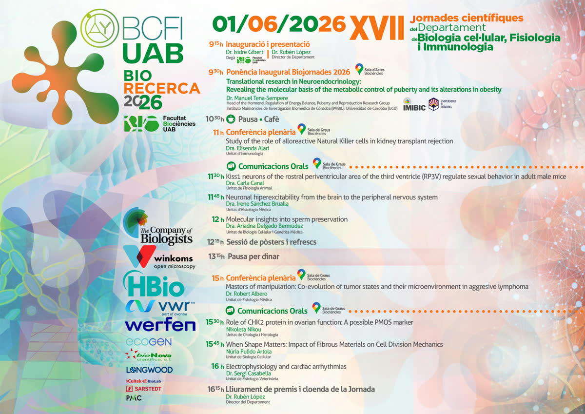
XI BABVE Scientific Conference 2026
On 1 June 2026, BABVE researchers will come together to share the most recent scientific output, as part of the XI Biorecerca Conference, taking place at the Sala de Graus of the Faculty of Biosciences (UAB).
We will showcase Parameciom Tracking Device designed for advanced microscopy applications.
Come and discover how the integration of motorised hardware and AI tools can transform your scientific workflows!
#microscopy #AI #biorecerca #UAB #BABVE #research #deepLearning #motorisation
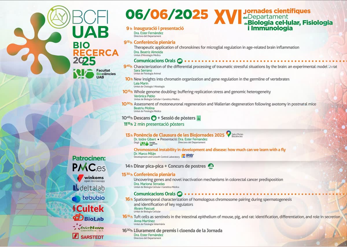
UABio 2025: presenting our technology solutions at the Faculty of Biosciences (UAB)
On 6 June 2025, we were present in Building C of the Faculty of Biosciences (UAB) at the UABio Scientific Conference, where we presented our technology solutions for research.
We showcased 2 motorised systems designed for advanced microscopy applications, as well as our web platforms:
Yolo Labeller Web App: a labeling tool for microscopy images based on YOLOv8 + SAM
QaiFIL Analysis Web App: a remote inference system optimised for quantifying filamentous bacteria.
Come and discover how the integration of motorised hardware and AI tools can transform your scientific workflows!
#microscopy #AI #cellBiology #UAB #research #deepLearning #motorisation #automatedAnalysis
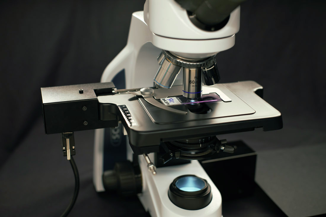
SimpleXYZ App SmartScopeLite
SimpleXYZ SmartScopeLite
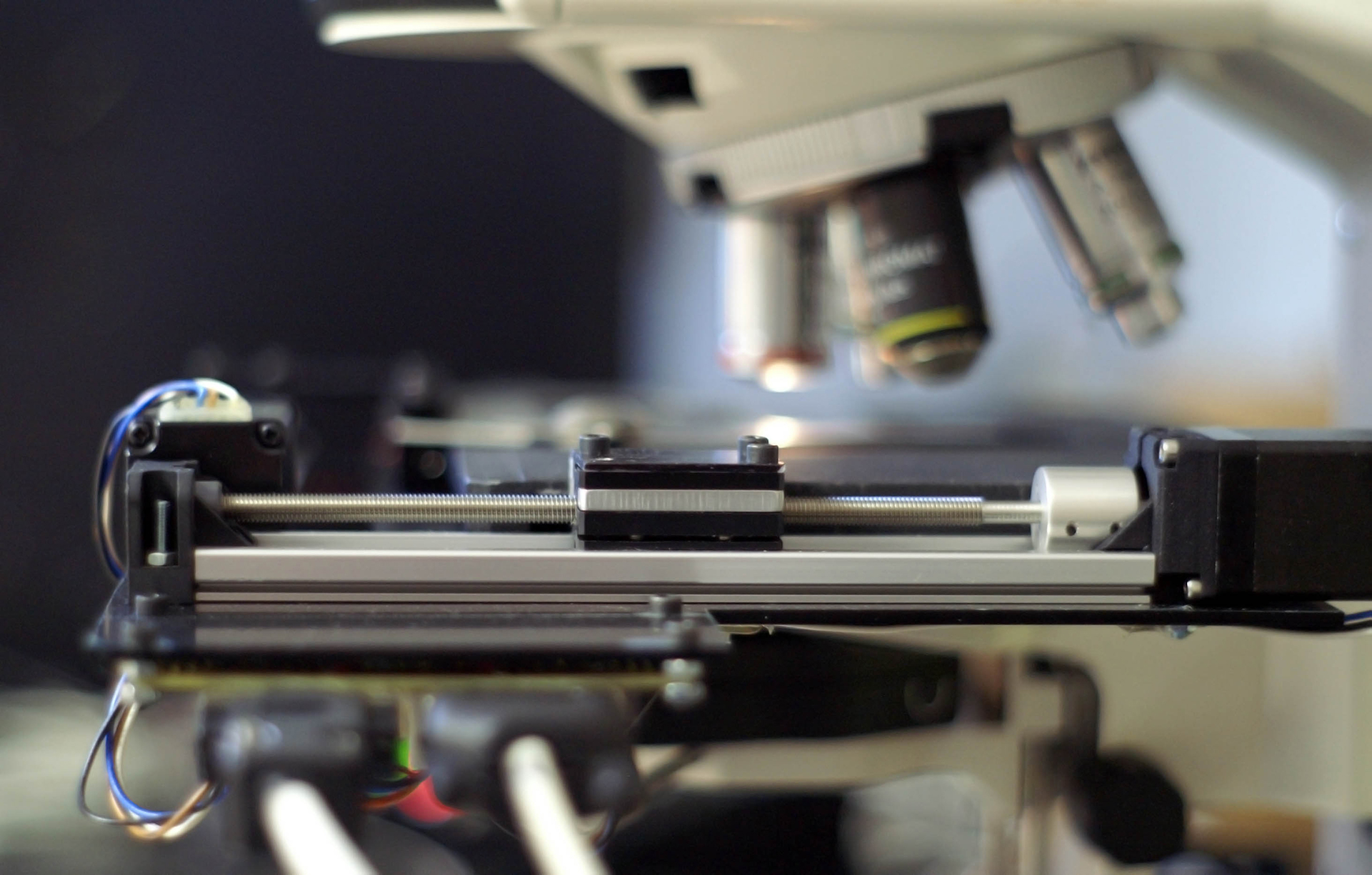
Winkoms have developed the motorized solution, software and hardware, of the SmartScopeLite for microscopiomotorizado.com
- Motorized image capture system. It has the capacity for up to 2 sample holders (75x25mm) per sample holder.
- Works with all microscopy techniques (transmitted light, epifluorescence, and materials).
- The system use autofocus algorithms and captures mosaics in arrays of images (3 axes X, Y, Z) without a limit on images.
- The software will generate the panoramic tiles images with a square spiral movement algorithm.
- All tiles can be Stitched easy with Fiji or Microscoft Image Composite Editor.
https://youtu.be/2tFzSpVen14
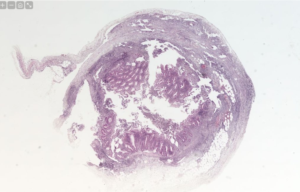
1GigaPixel Microscope Image Obj 20x/0.4
Mosaic Image Captured with SimpleXYZ Motorized Stage
Processed with Microscoft Image Composite Editor from Array of 17x17x3 total of 867 images
Microscope iScope
Objective 20x/0.4
What resolution should my microscope's digital camera have?
Original source: http://www.microscopiaoberta.com/?p=184&lang=ca
It's a classic for customers to ask me about digital cameras with 'the more megapixels, the better.' However, I always respond the same when they ask me this question:
The separating power (A.K.A. resolution) of a microscope is not given by the camera, is given by the objective of the microscope.
However, in the market, there are microscope cameras ranging from 1 to 32 megapixels, with 5 and 10 megapixels being common. But if the resolving power/resolution is not provided by the camera...
How many pixels are needed to work with microscopy?
Well, here I will present my proposal of mathematical demonstration, being as 'objective' as possible.
First point - The resolving power (A.K.A. Resolution) of a microscope
To determine HOW MANY pixels we need, we first need to know the resolving power of our microscopes.
This parameter is mainly determined by the Numerical Aperture of our objectives and is defined by the following simplified formula :

Form 1 Resolving Power [1]
Where:


Second point - Nyquist's Theorem
Now we have the resolution of our objectives, but how does this translate into pixels?
Well, for this, we have Nyquist's Theorem [2], which will determine the IDEAL pixel size for each of our objectives. I won't go into depth on the theorem; for more information, consult Wikipedia  .
.
A formula to calculate the IDEAL pixel size in microscopy is:

Form 2 Pixel Ideal Size µm [3]
| M | NA | p ideal, article (µm) | p Nyquist strict (µm) | ratio |
|---|---|---|---|---|
| 10 | 0.25 | 6.77 | 5.55 | 1.22 |
| 20 | 0.40 | 8.46 | 6.94 | 1.22 |
| 40 | 0.65 | 10.42 | 8.54 | 1.22 |
| 63 | 0.85 | 12.55 | 10.28 | 1.22 |
| 100 | 1.25 | 13.54 | 11.10 | 1.22 |
Where:

Now we add a column to our Resolving Power table with the Ideal Pixel column in µm:

Table Dimensions Pixel Size Ideal µm [3]
Third point - Camera Sensor Size
Now we know what dimensions our pixels need to have to resolve the images from our microscopes in maximum detail... but (there's always a 'but') how do we translate the size of 1 pixel into the resolutions we use with our cameras?
The simplest way to calculate is:

Form 3 Dimension Pixel Ideal
Where we consider that pixels are SQUARE.
For a theoretical sensor with a 1-inch diagonal and a 4/3 aspect ratio, we obtain:

Table Maximum Megapixels For each magnification
| Format | Literal diagonal (used in this article) | Real dimensions |
|---|---|---|
| 1" | 25.4 mm | 12.8 × 9.6 mm (diagonal ≈ 16 mm) |
| 1/2" | 12.7 mm | 6.4 × 4.8 mm |
| 1/3" | 8.47 mm | 4.8 × 3.6 mm |
| 1/2.5" | 10.16 mm | 5.76 × 4.32 mm |
As a result, every "maximum megapixels" table in this article is inflated by roughly 2–2.5×. With real sensor dimensions, a 1/3" sensor at M=10 supports about 0.56 MP, not the much larger figure implied by a literal 25.4 mm diagonal — modern 1/3" microscopy sensors (2–4 µm pixels) intentionally oversample relative to the "ideal pixel" computed here. Always use the real physical dimensions of your specific camera sensor model, not the inch label, when sizing a camera.
| M | NA | p Nyquist (µm) | 1/3" real (4.8×3.6) | 1/2" real (6.4×4.8) | 1" real (12.8×9.6) |
|---|---|---|---|---|---|
| 10 | 0.25 | 5.55 | 0.56 MP | 1.00 MP | 3.99 MP |
| 20 | 0.40 | 6.94 | 0.36 MP | 0.64 MP | 2.55 MP |
| 40 | 0.65 | 8.54 | 0.24 MP | 0.42 MP | 1.69 MP |
| 63 | 0.85 | 10.28 | 0.16 MP | 0.29 MP | 1.16 MP |
| 100 | 1.25 | 11.10 | 0.14 MP | 0.25 MP | 1.00 MP |
Above the MegaPixels value obtained, we will be oversampling the image and NOT OBTAINING MORE INFORMATION, just bigger/larger spots with more pixels but not more 'resolved' images/information.
Below this value, we do LOSE INFORMATION, and it is not recommended at all (if we can avoid it, of course!).
An important detail to consider here is that our sensor doesn't have ANY additional optical element that could modify the dimensions of the sensor.
In the case that our microscope has a 0.63x or 0.5x adapter for the camera, we will need to recalculate the sensor size with the following formula:

Form 4 RealSensorSize/Magnificaion Adapter camera
Example of a 1/3" with a 0.5x optical camera adapter:

Let's compare the results of the maximum MegaPixels with and without the optical camera adapter:
Table: Maximum Megapixels for a 1/3" Sensor Camera with 1x adapter:

Table: Maximum Megapixels for a 1/3" Sensor Camera with 0.5x adapter

Here we see the dual utility of optical adapters for cameras in microscopes because, in addition to increasing the 'field' of our image, they also allow us to obtain images at higher 'megapixels,' at the cost of losing magnification, of course!
Notes:
This Ideal Pixel dimension and all the tables presented so far correspond to a MONOCHROME sensor.
RGB camera sensors, which usually have a color filter with a Bayer pattern, the usable pixel does NOT correspond to the pixel size provided by the manufacturer because it is necessary to apply DeMosaicing [4] (color interpolation) to obtain a pixel with the correct RGB color, altering the effective pixel size according to the DeMosaicing method/algorithm applied, with typical factors between 1.25x and 2x depending on the method used.
Only monochrome sensors meet the nominal Nyquist pixel size computed above. For RGB/Bayer sensors, multiply the strict Nyquist pixel size by the demosaicing factor (pBayer ≈ 2 × pNyquist for standard bicubic interpolation).
- The full system MTF is a product: MTFsystem = MTFoptics × sinc(p·f) × fill factor — this is the framework that explains why the "ideal pixel" is not an all-or-nothing threshold.
- This criterion assumes well-adjusted Köhler illumination (condenser NA ≥ objective NA); with a closed condenser, coherence increases and the cut-off shifts to NA/λ (coherent illumination).
Thanks for your attention
F.Xavier Gómez
References
[1] https://en.wikipedia.org/wiki/Optical_resolution
[2] https://en.wikipedia.org/wiki/Nyquist-Shannon_sampling_theorem
[3] http://www.microscopyu.com/tutorials/java/digitalimaging/pixelcalculator/
[4] https://en.wikipedia.org/wiki/Demosaicing
All information published here is under the license Creative Commons Attribution-NonCommercial 4.0 International License.
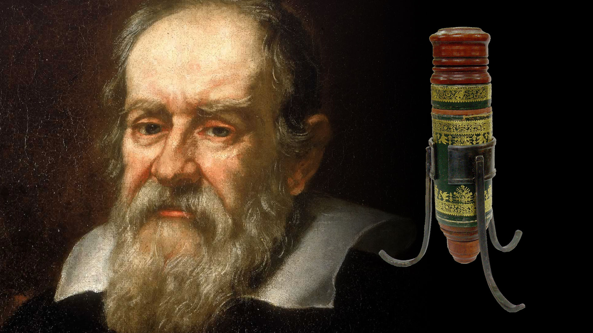
Galileo Galilei and Winkoms
Although Galileo Galilei did not stand out especially for his microscopic studies, he did so because of the application of the lenses in several devices such as the telescope and the creation of a microscope which he called "occhiolino" in the year 1609.
"The occhiolino" or microscope composed of a convex lens and a concave lens had a finish, cover included, with a strong Italian Renaissance character.
The microscope was made up of three lenses: eyepiece, field and objective. The eyepiece was located in a wooden capsule inserted in the upper part of the inner cardboard cylinder. At the bottom of this cylinder, held by a wooden ring, was the field lens. With respect to the objective lens it was in a wooden support at the bottom of the outer cylinder and lined with green leather. The inner cylinder (eyepiece and field) slides inside the outer one, to calculate the focal. The external cylinder, with the entire optical system was supported by an iron ring supported by three pillars. The approach was achieved by moving the body inside the iron ring.
Our brand Winkoms wants to pay tribute to the "occhiolino" (wink in English) of Galileo Galilei, and we intend that its creation and ingenuity be the reflection of our values and the way of understanding business.